 Route 01
LMD / DED
Route 01
LMD / DED
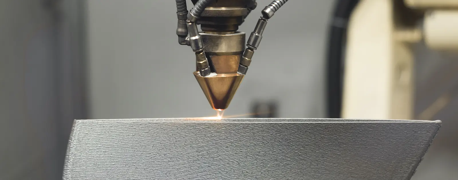
Choose deposition when the value is scale, local material addition, repair, modification or cladding on an existing part.
Technology
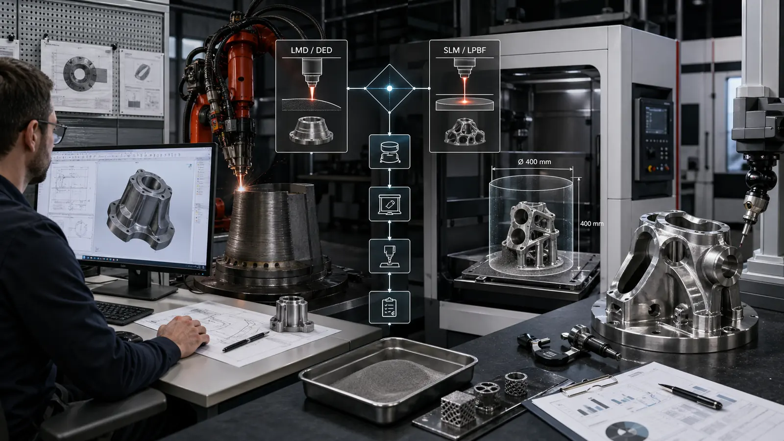
Exafuse compares laser-based metal additive routes by part size, feature detail, repair need, performance target, finishing plan and inspection scope.
LMD, SLM, hybrid
Exafuse uses a process-selection roadmap: LMD for scale and local material addition, SLM for fine powder-bed geometry, and hybrid routes when one workflow alone is not the best answer.
Route 01
LMD / DED
Choose deposition when the value is scale, local material addition, repair, modification or cladding on an existing part.
 Route 02
SLM / LPBF
Route 02
SLM / LPBF
Choose powder-bed fusion when compact geometry, internal channels, lattices or fine detail create the value.
 Route 03
Hybrid route
Route 03
Hybrid route
Combine LMD scale or repair logic with SLM detail when a single process would force the wrong compromise.
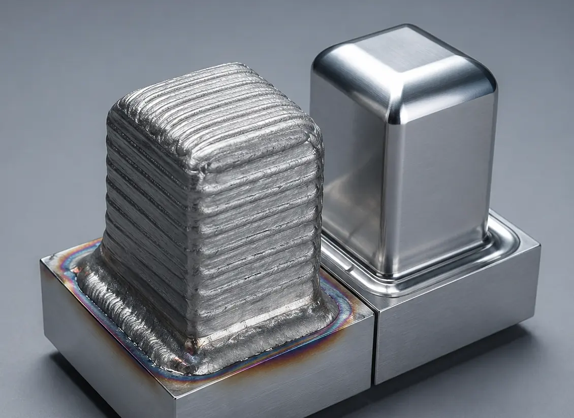
A high-energy laser creates a melt pool. Metal powder is fed into that pool and deposited along a defined path. This is the core route for large components, repair, modification and laser cladding.
Open related page
A precise laser fuses regions of a metal powder bed layer by layer from CAD data. This route is strongest when compact geometry, internal features or fine detail create the part value.
Open related page
When required, the route can combine LMD scale, speed or local build-up logic with SLM resolution logic. The decision is tied to performance, cost, finishing and qualification risk.
Open related pageProcess chain
Every LMD, SLM or hybrid project connects process planning, material choice, build strategy, finishing and inspection. Treating them together makes feasibility clearer from the first review.
Large structural LMD proof
Large LMD capability is credible only when geometry, path planning, monitoring, parameter development, finishing and validation are connected. The Duisburg bridge components give that proof path in one project.
Capabilities and equipment
The equipment story is shown once here: two LMD routes for scale and geometry, SLM / LPBF for compact detail, post-processing, quality support and data-led process understanding.
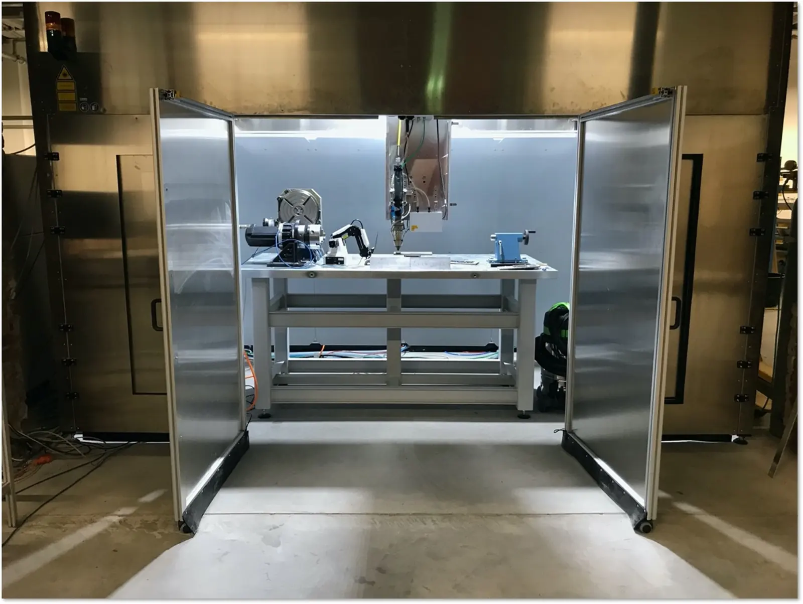
3-axis Titan LMD
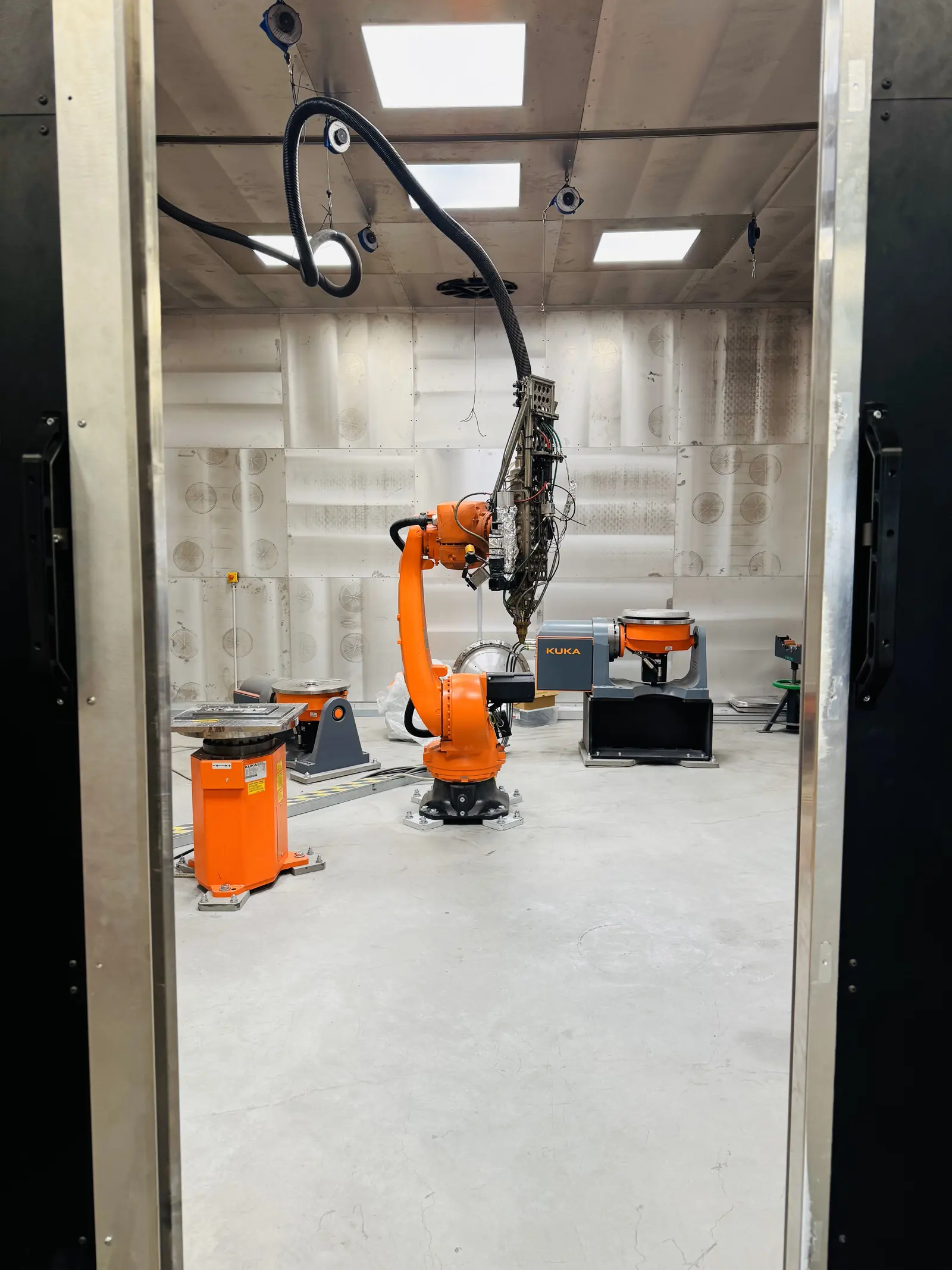
6-axis robotic LMD
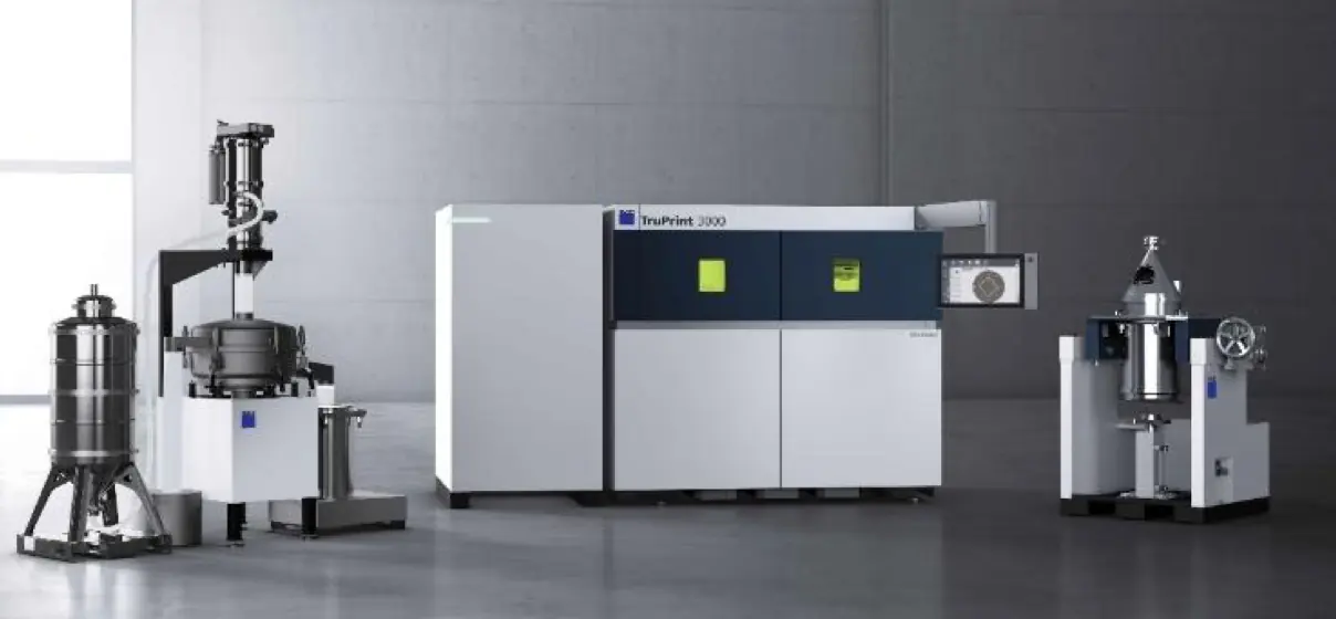
SLM / LPBF machine
Post-processing
Quality support
Computing / AI
Thin-wall and multi-material LMD
A 750 mm water-cooled nozzle design produced by LMD used Inconel 625 in the inner structure and Inconel 718 in the outer structure and cooling ribs. The proof story is useful because it shows material zones, path planning and long-build stability together.
Integrated LMD workflow
A public Exafuse video shows a 130 mm drill where LMD is used for both fabrication from powder and final wear-resistant anti-magnetic coating from an alloy containing tungsten carbide. The technology lesson is route planning, not a universal one-process promise.
Research connection
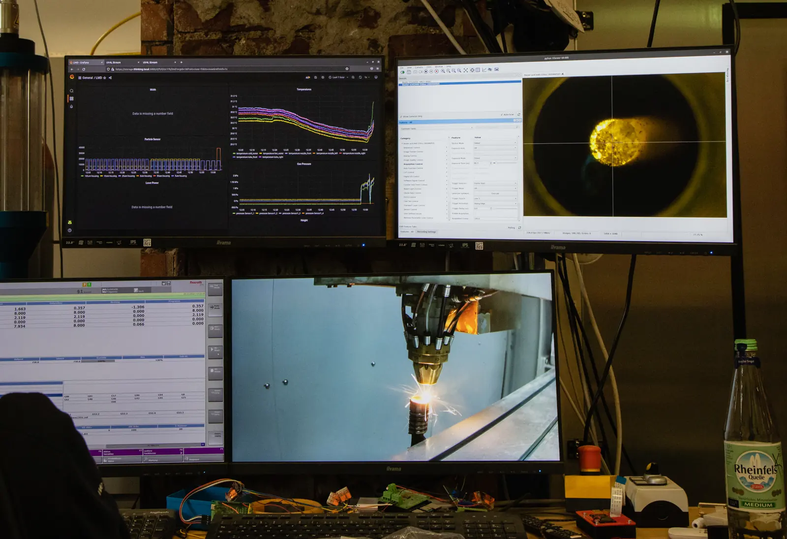
Wide-bead deposition, rotating multispot optics, dynamic powder feeding and sensor-supported process control are research themes that help explain where large-part LMD productivity can improve.
Quality and inspection
Inspection planning defines what is checked, what evidence is produced, and which acceptance criteria matter for the part function.
Dimensional restoration, machining allowance and final datum plan.
Open related page
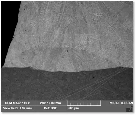
Bond quality, dilution, microstructure and heat-affected zone when in scope.
Open related page
Porosity, cracking and other risks are addressed through process planning and suitable inspection.
Open related page
Inspection outputs and evidence packs are matched to buyer and project requirements.
Open related page